
| Full title | IEEE 802.3af-2003 (DTE Power via MDI) and IEEE 802.3at-2009 (DTE Power via MDI Enhancements) |
| Publisher | IEEE Standards Association, 802.3 Working Group |
| Approved | 802.3af: June 2003. 802.3at: 11 September 2009 |
| Status | Both incorporated into the base IEEE 802.3 standard, Clause 33 |
| Common names | 802.3af = PoE (Type 1). 802.3at = PoE+ (Type 2) |
| Extended by | IEEE 802.3bt (Type 3 and Type 4, four-pair), Clause 145 |
What the standards cover
IEEE 802.3af defined how power sourcing equipment (PSE), such as a PoE switch or midspan injector, delivers DC power to a powered device (PD), such as a phone, camera or access point, over the same twisted-pair cable that carries the data. 802.3at raised the power and added Type 2. Both are now part of IEEE 802.3, Clause 33.
The standards distinguish an endpoint PSE, where power is supplied from the switch port itself (usually called an endspan), and a midspan PSE, which sits between the switch and the device and adds power to the link.
Type 1 and Type 2 compared
| Parameter | Type 1 (802.3af) | Type 2 (802.3at) |
|---|---|---|
| Minimum output at the PSE | 15.4 W | 30 W |
| Maximum power at the PD | 12.95 W | 25.5 W |
| PSE output voltage | 44 to 57 V DC | 50 to 57 V DC |
| PD input voltage | 37 to 57 V DC | 42.5 to 57 V DC above 12.95 W (37 to 57 V at or below) |
| Maximum current per pair | 350 mA | 600 mA |
| Maximum DC loop resistance per pair | 20 Ω | 12.5 Ω |
| Pairs carrying power | 2 | 2 |
| Cabling assumed by the standard | 10BASE-T grade cabling (Category 3), with Class D recommended | ISO/IEC 11801 Class D (Category 5 or better) |
| Maximum channel length | 100 m | 100 m |
Which pairs carry power
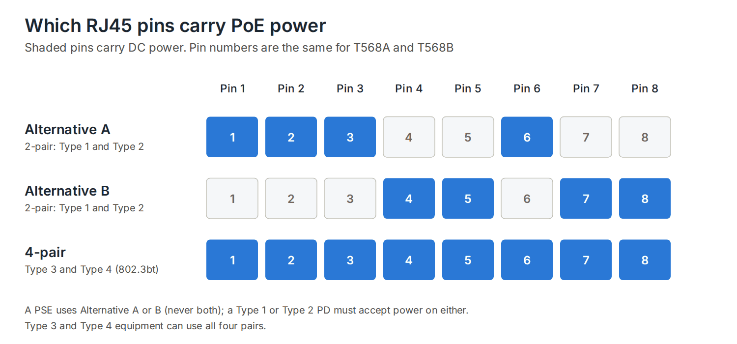
A PSE supplies power on one of two pair sets. Alternative A uses the pairs on pins 1 and 2 and pins 3 and 6; Alternative B uses the pairs on pins 4 and 5 and pins 7 and 8. A PSE uses one alternative, never both. A Type 1 or Type 2 PD must accept power on either alternative and in either polarity, so the installer does not need to know which the PSE uses.
Power classes
| Class | Minimum output at the PSE | Power at the PD | PD classification current |
|---|---|---|---|
| 0 | 15.4 W | 0.44 to 12.95 W | 0 to 4 mA |
| 1 | 4.0 W | 0.44 to 3.84 W | 9 to 12 mA |
| 2 | 7.0 W | 3.84 to 6.49 W | 17 to 20 mA |
| 3 | 15.4 W | 6.49 to 12.95 W | 26 to 30 mA |
| 4 (Type 2 only) | 30 W | 12.95 to 25.5 W | 36 to 44 mA |
The difference between the PSE output and the PD power is the allowance for loss in up to 100 m of cable at the maximum loop resistance.
How a PSE detects and powers a device
- Detection: the PSE applies a low voltage (in the range 2.7 to 10.1 V at the PD) and looks for a signature resistance of about 25 kΩ (23.75 to 26.25 kΩ). Devices without a valid signature, such as a laptop’s network port, are not powered.
- Classification: the PSE raises the voltage (14.5 to 20.5 V at the PD) and measures the current the device draws, which tells it the device’s class.
- Type 2 devices: a Type 2 PSE confirms a Class 4 device either with a two-event physical classification or through the data link layer using LLDP. Until it does, the device must not draw more than Type 1 power.
- Power on: the PSE applies full voltage and keeps monitoring. If the device is unplugged, the PSE removes power.
Cable temperature
Current flowing in the conductors heats the cable, and the effect is greater in bundles. IEEE 802.3 Clause 33 states that, in the worst case, Type 2 operation needs a 5 °C reduction in the maximum ambient operating temperature of the cable when half the pairs carry full current, which is normal for two-pair PoE, or 10 °C if all pairs do. It refers to ISO/IEC TR 29125 (now ISO/IEC TS 29125) and TIA TSB-184 for guidance on bundles.
Read PoE vs PoE+ vs PoE++ for a plain-English comparison of the three generations.