Structured cabling is the term for a building’s permanent telecommunications wiring infrastructure — the cables, outlets, patch panels, and distribution equipment that form the physical foundation every networked device in the building relies on. It is the layer of infrastructure that exists before the network switches, servers, and devices are installed, and it is what those devices connect to. When it is designed and installed correctly, it is invisible — it just works, for decades, regardless of how many times the network equipment above it changes. When it is done badly, it becomes the source of intermittent faults, performance problems, and expensive remedial work.
This guide explains what structured cabling is, how it is organised, what the key components are, and what to consider when specifying or commissioning a structured cabling installation.
What structured cabling actually means
Before structured cabling standards existed, buildings were wired in a point-to-point fashion — each device had its own dedicated cable run back to the equipment it connected to. Telephone systems used one type of cable, different computer systems used entirely different cabling, and none of it was designed to be reused or repurposed. When systems changed, the cabling had to change with them.
Structured cabling replaced this approach with a standardised, hierarchical infrastructure designed to be application-independent. The same physical cabling plant supports voice, data, building management systems, and other services — not through any single cable doing all of those things simultaneously, but through a common infrastructure of outlets, patch panels, and distribution equipment that can be patched and re-patched at will to connect any outlet to any service without touching the cables inside the walls.
The design principles and performance requirements for structured cabling systems are defined in ISO/IEC 11801, the international standard for generic telecommunications cabling. In Europe, the equivalent standard is EN 50173. These standards define the categories of cable, the maximum distances, the number of connection points permitted in a channel, the testing requirements, and the documentation that must be produced on completion. A compliant structured cabling installation is one that has been designed, installed, tested, and documented to meet these standards — and that comes with test certification to prove it.
The six subsystems
Structured cabling is organised into six defined subsystems, each with a specific role in the overall infrastructure. Understanding these subsystems is the foundation for understanding how any structured cabling system is designed.
1. Entrance facility
The entrance facility is where external cabling — from the internet service provider, a private WAN connection, or a link to another building — enters the building. It is the demarcation point between the public or external network and the building’s private infrastructure. In most commercial buildings this is a dedicated cabinet or room near the building entry point, housing the incoming fibre or copper termination and the first point of connection to the internal backbone.
2. Equipment room
The equipment room is the building’s main communications hub — the space that houses the core network switches, servers, patch panels, and other active equipment. It is typically climate-controlled, with managed power and physical access control. In smaller buildings there may be a single equipment room; in larger ones it houses the main distribution frame that connects to multiple telecommunications rooms across the building. This is where the building’s backbone cabling terminates and where connections to the external network are made.
3. Backbone cabling
Backbone cabling — sometimes called vertical or riser cabling — provides the high-capacity links between the equipment room and the telecommunications rooms on each floor. In multi-storey buildings, backbone cables run vertically through risers or cable shafts. In campus environments they run between buildings. Backbone cabling typically uses fibre optic cable for its bandwidth, distance, and electromagnetic immunity advantages, though high-grade copper can be used over shorter backbone runs. The backbone carries aggregated traffic from all devices on each floor, so its capacity is sized accordingly.
4. Telecommunications room
Each floor or zone of a building typically has its own telecommunications room — sometimes called a comms room, IDF (intermediate distribution frame), or floor distributor. This is where the backbone cabling from the equipment room terminates, and where the horizontal cabling to individual workstations and outlets fans out. The telecommunications room houses the floor-level patch panels, switches, and cable management equipment. The location of telecommunications rooms on each floor directly determines how far the horizontal cabling has to run to reach each outlet — which is why their placement is a critical early decision in the design process.
5. Horizontal cabling
Horizontal cabling is the permanent installed cable that runs from the telecommunications room to each individual outlet in the work area — through ceiling voids, wall cavities, floor ducts, and containment. This is the layer of the infrastructure that most people are aware of, even if they do not know its name. It is typically Cat6 or Cat6A copper cable in most modern commercial installations. The maximum permitted length for horizontal cabling under ISO/IEC 11801 and ANSI/TIA-568 is 90 metres — this is the permanent link, measured from the patch panel in the telecommunications room to the outlet faceplate at the desk or on the wall.
6. Work area
The work area is the end point of the structured cabling system — the outlet faceplate, the keystone jack it contains, and the patch cord that connects a device to the outlet. The work area patch cord is the only part of the structured cabling infrastructure that changes regularly, as devices are moved, replaced, or reconfigured. The 90-metre permanent link plus up to 10 metres of patch cordage at both ends gives a maximum total channel length of 100 metres — the figure that governs the layout of telecommunications rooms relative to the furthest outlets they need to serve.
The 90 metre rule explained
The 90-metre limit for horizontal cabling is one of the most fundamental constraints in structured cabling design, and understanding why it exists helps explain many of the decisions made during installation. At 100 metres total channel length — 90m of permanent link plus 10m of patch cords — the signal attenuation, crosstalk, and delay characteristics of Cat5e, Cat6, and Cat6A copper cable at Gigabit Ethernet frequencies fall within the performance envelope required for reliable transmission. Beyond 100 metres, performance degrades in ways that cannot be compensated for by better cable or connectors.
This constraint means that the maximum distance between any telecommunications room and the furthest outlet it serves must be no more than 90 metres of cable — not 90 metres of straight-line distance, but 90 metres of actual cable route, which is always longer due to the path cable takes through containment, around obstacles, and down walls. On large floor plates, this often means multiple telecommunications rooms per floor rather than one central room. Getting the telecommunications room locations right at the design stage is far cheaper than discovering outlets that exceed 90 metres after installation.
Copper vs fibre in structured cabling
Modern structured cabling systems use copper for horizontal cabling and fibre for backbone cabling in the majority of commercial installations — though fibre-to-the-desk is increasingly specified in high-performance and data-intensive environments.
Cat6 is the current standard minimum for new horizontal cabling installations, supporting Gigabit Ethernet to the full 100-metre channel and 10 Gigabit Ethernet to around 55 metres depending on the alien crosstalk environment. Cat6A extends 10 Gigabit capability to the full 90-metre permanent link and is the recommended specification for new installations where future bandwidth requirements are uncertain — which is most of them. The additional cost of Cat6A over Cat6 at installation time is significantly less than the cost of recabling a building later.
DTECH’s Cat6 UTP cable is rated to 500MHz and supports 10GBase-T to the full 90-metre permanent link — beyond the standard Cat6 specification — as well as PoE++ (IEEE 802.3bt) for high-power device deployments including wireless access points, PTZ cameras, and digital signage. The LSZH violet jacket makes it appropriate for permanent installation in commercial buildings and straightforward to identify alongside other cable types in mixed installations.
Fibre backbone cabling uses OM4 multimode for intra-building runs and OS2 single mode for longer inter-building and campus links. Fibre carries aggregated floor traffic at speeds that copper backbone cannot match over the same distances, and is immune to the electromagnetic interference that affects copper over longer runs through plant rooms and riser shafts.
Why standards compliance matters
A structured cabling installation that has been designed and installed to ISO/IEC 11801 or EN 50173 — and certified with field test results for every link — provides a documented, warranted physical infrastructure that will support network applications reliably over the designed lifetime of the system. Most structured cabling manufacturers offer extended system warranties of 25 years against component and system performance, provided the installation is carried out by a certified installer using compliant components and is tested and documented on completion. DTECH offers a 30-year warranty to trade partners on qualifying installations, reflecting the performance headroom built into the cable specifications across the range.
An installation that lacks test certification has no verifiable performance baseline. When faults occur — and in any system of sufficient size and age, faults will occur — untested and undocumented installations are significantly harder and more expensive to diagnose and remediate. Test certification is not a bureaucratic requirement; it is the proof that the physical infrastructure will do what the network applications above it need it to do.
Standards compliance also determines what applications the infrastructure can support. A certified Cat6A installation can be relied upon to support 10 Gigabit Ethernet, PoE++, and any other application within Cat6A’s specification for the lifetime of the installation. An uncertified installation of unknown performance cannot make that guarantee — and the difference often only becomes apparent when a new application is deployed and performance falls short.
Structured cabling components
A complete structured cabling system is made up of several distinct component types that work together as a system:
Bulk cable is the installed horizontal and backbone cabling — the solid-core copper or fibre that runs permanently through walls and ceiling voids. Cat6 and Cat6A are the current standards for copper horizontal cabling. OM4 covers multimode fibre backbone for intra-building runs; OS2 covers single mode for longer campus and inter-building links.
Keystone jacks are the modular connectors installed in outlet faceplates at the work area end of the horizontal cable. The jack terminates the solid core horizontal cable and presents an RJ45 socket to the user. The category rating of the keystone jack must match or exceed the category of the cable — a Cat6 cable terminated into a Cat5e jack produces a Cat5e link regardless of the cable specification.
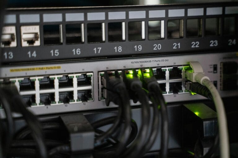
Patch panels are the termination points at the telecommunications room end of the horizontal cabling. Each horizontal cable terminates at a numbered port on the patch panel, and patch cords connect those ports to the network switch. The patch panel is what makes the infrastructure flexible — changing which outlet connects to which switch port is a matter of moving a patch cord, not touching the installed cabling.
Patch cords are the stranded flexible cables used at both ends of the channel — from patch panel to switch in the telecommunications room, and from outlet to device in the work area. Unlike the solid-core permanent link, patch cords are flexible and designed to be connected and disconnected repeatedly.
Cable management — containment, trunking, cable ladders, and basket tray — routes and protects the installed cabling from the equipment room through risers and ceiling voids to each outlet. Good cable management is what makes an installation maintainable: cables that are correctly routed, supported, and labelled can be traced, tested, and modified years after installation without difficulty.
Frequently asked questions
How long does a structured cabling installation last?
A properly installed and certified structured cabling system typically has a design life of 25 years or more, and many installations significantly outlast that. The physical cable plant — the horizontal and backbone cabling inside the building fabric — rarely needs replacing. What changes over time is the active equipment connected to it: switches, patch panels, and occasionally keystone jacks and patch cords. A Cat6A installation installed today should be capable of supporting whatever network applications are deployed against it well into the foreseeable future, since Cat6A’s 10 Gigabit capability at 90 metres comfortably exceeds the access layer requirements of most commercial networks currently being designed.
What is the difference between Cat6 and Cat6A for structured cabling?
Standard Cat6 supports Gigabit Ethernet to the full 100-metre channel and 10 Gigabit Ethernet to around 55 metres. Cat6A supports 10 Gigabit Ethernet to the full 90-metre permanent link. DTECH’s Cat6 cable is rated to 500MHz and supports 10GBase-T to the full 90 metres — beyond the standard Cat6 specification — making it a strong choice for installations where Cat6A budget is not available but full 10G reach is required. For new installations where 10GBase-T at full channel length is a firm requirement, Cat6A remains the recommended specification.
Does structured cabling support PoE?
Yes — Power over Ethernet is delivered through the same copper horizontal cabling as data. PoE, PoE+ and PoE++ (IEEE 802.3bt) all operate over Cat5e, Cat6, and Cat6A infrastructure. Higher power PoE applications generate more heat in bundled cable runs, which is one reason Cat6A — with its larger conductor cross-section and lower resistance — is preferred for high-density PoE installations such as wireless access point and IP camera deployments. DTECH’s Cat6 cable is rated for PoE++ and its 500MHz specification provides additional headroom for demanding deployments.
Can I add to an existing structured cabling installation?
Yes, structured cabling is designed to be extended. New horizontal runs can be added to existing patch panels or additional patch panels installed in existing telecommunications rooms, provided the room has capacity. The key requirement is that new cabling is installed and tested to the same standard as the existing infrastructure, and that the test records are added to the installation documentation. Adding uncertified cabling to a certified system undermines the integrity of the overall installation.
What is the difference between a channel and a permanent link?
The permanent link is the fixed installed portion of the cabling channel — the horizontal cable from patch panel port to outlet faceplate, maximum 90 metres. The channel is the complete end-to-end signal path including the patch cords at both ends, maximum 100 metres total. Permanent link testing is carried out by the installer at completion, using calibrated test equipment that excludes the patch cords. Channel testing includes the patch cords and verifies performance under operational conditions. Both are valid tests for different purposes: permanent link testing certifies the installed infrastructure, channel testing verifies end-to-end application performance.
Summary
Structured cabling is the organised, standards-compliant physical wiring infrastructure that every networked building relies on. It is built from six subsystems — entrance facility, equipment room, backbone cabling, telecommunications rooms, horizontal cabling, and work area — each with defined performance requirements and maximum distances. The 90-metre permanent link rule is the central constraint that shapes telecommunications room placement and installation design. Cat6A copper for horizontal cabling and OM4 or OS2 fibre for backbone represent current best practice for new commercial installations. Test certification to ISO/IEC 11801 or EN 50173 is what converts an installation from a collection of cables into a warranted, documented infrastructure.
If you need help specifying copper or fibre cable for a structured cabling installation, get in touch with the DTECH team — we supply Cat6, Cat6A, OM4, and OS2 cabling systems to installers and IT teams across the UK, Europe, and the Middle East.