Insertion loss and return loss are the two parameters that define how well a fibre optic link will actually perform — and they are the two figures that appear on every fibre test report, every product datasheet, and every discussion of link budget. They measure different things, they are expressed in opposite directions (one wants to be low, the other wants to be high), and confusing the two — or not understanding what drives them — is a common source of misdiagnosed fibre problems on site.
This guide explains what insertion loss and return loss actually are, what typical values look like for OM4 and OS2, what drives each one, and how to think about them when specifying or troubleshooting a fibre link.
Insertion loss — the light that doesn’t arrive
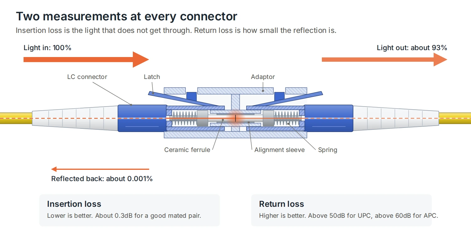
Insertion loss (IL) is the reduction in optical power as light travels through a fibre link — from the fibre itself, and from every connector, splice, and component the light passes through on the way. It is calculated as 10 times the base-10 logarithm of the ratio of input power to output power, expressed in decibels as a positive number. A lower insertion loss figure is always better — it means more of the transmitted light actually reaches the receiver at the far end.
Insertion loss has several sources that combine along a link. The fibre itself has an inherent attenuation per kilometre, driven by Rayleigh scattering and absorption in the glass — this is a fixed physical property of the fibre type and the wavelength being used. Every connector pair adds loss at the mated interface, typically around 0.3dB for a good-quality connector, caused by microscopic core misalignment, air gaps, or surface imperfections at the polished end face. Every splice adds a smaller amount — a well-executed fusion splice typically adds only 0.02 to 0.05dB, making it a far lower-loss joining method than a mechanical connector. Bends below the fibre’s specified minimum bend radius also add loss, as light escapes the core at the point of the bend.
Because insertion loss is cumulative, a fibre link’s total loss budget is calculated by adding together fibre attenuation over the link length, the loss from every connector pair, and the loss from every splice, then comparing that total against the transceiver’s available optical power margin — the difference between what the transmitter sends and the minimum power the receiver needs to correctly decode the signal. If total insertion loss exceeds the available margin, the link will experience errors or fail entirely, even though every individual component might be within its own specification.
Return loss — the light that bounces back
Return loss (RL), sometimes called reflectance, measures the proportion of light reflected back towards the transmitter at a connection point, rather than passing through. It is also measured in decibels, but unlike insertion loss, a higher return loss figure is better — a high number means very little light is being reflected back, which is the desired outcome. Return loss is typically expressed as a value between -15dB and -60dB depending on connector polish type, with industry standards generally requiring PC (physical contact) connectors to exceed 50dB and APC (angled physical contact) connectors to exceed 60dB.
Reflections occur wherever there is a discontinuity in the fibre path — most significantly at connector interfaces, where even a microscopic air gap or surface imperfection on the polished end face causes some light to bounce back rather than transmit through. Scratches, pits, and particle contamination on a connector end face all increase reflected light and reduce return loss. Reflected light travelling back towards the transmitter is not simply wasted power — it can destabilise laser sources, particularly in single-mode systems using narrow-linewidth lasers for long-haul or high-speed transmission, where reflected light re-entering the laser cavity can cause noise and instability in the transmitted signal itself.
This is why return loss is a specific and important concern for OS2 single-mode applications in particular — long-distance transmission, CWDM, DWDM, and high-speed applications where laser stability directly affects signal quality. It is a less critical parameter for OM4 multimode, which typically uses VCSEL sources that are less sensitive to back-reflection than the narrow-linewidth lasers used in demanding single-mode applications.
Insertion loss and return loss for OM4
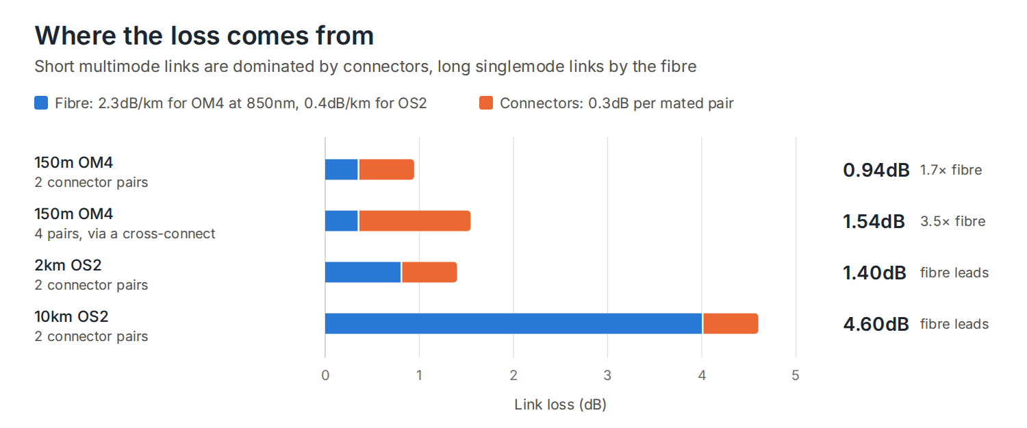
OM4 multimode fibre has an inherent attenuation of approximately 2.3dB/km at 850nm — the wavelength used by standard VCSEL transceivers — and a much lower 0.6dB/km at 1300nm. Because OM4 is specified for relatively short intra-building and campus backbone distances — up to 550m at 10G, 150m at 40G/100G — total fibre attenuation over the link length is rarely the limiting factor. In a typical 150m OM4 backbone run, fibre attenuation alone contributes roughly 0.35dB — a small fraction of the total loss budget compared to connector loss.
This is why connector quality and count matter proportionally more on OM4 links than on longer single-mode runs. Every connector pair adds around 0.3dB, and on a typical structured cabling channel with connections at the patch panel at each end, plus any intermediate cross-connects, the cumulative connector loss can exceed the fibre attenuation itself several times over. Because OM4 typically uses standard 850nm VCSEL sources that are not highly sensitive to back-reflection, return loss is a less critical specification for most OM4 applications than it is for OS2 — though maintaining good connector end-face quality remains important for overall link reliability.
DTECH’s OM4 tight buffered bulk cable paired with factory-terminated OM4 pigtails keeps connector-related insertion loss to a minimum — factory polishing consistently delivers lower and more predictable loss than field-polished connectors, which matters most on shorter OM4 links where connector loss is the dominant contributor to the total loss budget.
Insertion loss and return loss for OS2
OS2 single-mode fibre has a maximum attenuation of 0.4dB/km at both 1310nm and 1550nm under ISO/IEC 11801 — significantly lower than OM4’s per-kilometre loss, which is exactly why OS2 is specified for the long inter-building, campus, and metro distances that multimode cannot cover. Over a 2km campus link, for example, OS2 fibre attenuation contributes less than 1dB — a small figure that leaves substantial margin for connectors, splices, and future link extension.
Because OS2 is used for longer runs and often for higher-speed, longer-reach applications — 10G, 40G, and 100G Ethernet over distances measured in kilometres, as well as CWDM and DWDM systems carrying multiple wavelengths on a single fibre — return loss becomes a much more significant specification than it is for OM4. Reflected light in these systems can degrade the stability of the narrow-linewidth lasers commonly used, making connector polish type a meaningful specification decision rather than a minor detail.
This is the core reason APC (angled physical contact) connectors exist and are the standard for demanding OS2 applications — the 8-degree angled end face directs any reflected light out of the fibre core at an angle, rather than straight back towards the source, dramatically improving return loss compared to UPC connectors. DTECH’s OS2 SC APC patch leads are specified for exactly this kind of high-return-loss requirement — long-distance, PON, and DWDM applications where reflected light must be minimised. For standard OS2 data applications where return loss sensitivity is lower, DTECH’s OS2 LC UPC patch leads provide the marginally lower insertion loss that UPC’s flat, direct-contact polish delivers.
Why polish type changes both figures
UPC and APC connectors trade off insertion loss and return loss in opposite directions, which is why understanding both parameters together — rather than optimising for one in isolation — matters when specifying connectors. UPC connectors have the smallest air gap and the most direct core-to-core contact, giving them the lowest typical insertion loss of the common polish types. APC connectors have a very slightly higher typical insertion loss due to the angled interface, but dramatically better return loss — often 60dB or higher, compared to the 50dB threshold typical of UPC.
The practical rule: UPC is the standard choice where insertion loss is the primary concern and reflection sensitivity is low — most OM4 multimode links and standard OS2 data applications. APC is required where return loss matters — any application with a laser source sensitive to back-reflection, which in practice means most demanding OS2 single-mode applications: PON, FTTH, CWDM, DWDM, and long-haul transmission. UPC and APC connectors are never intermateable — connecting a UPC patch lead to an APC adaptor, or vice versa, damages the angled end face and produces unacceptably high loss on both parameters. The entire channel must use one polish type throughout.
OM4 vs OS2 loss characteristics at a glance
| OM4 multimode | OS2 single mode | |
|---|---|---|
| Attenuation at primary wavelength | ~2.3dB/km at 850nm | 0.4dB/km max at 1310nm/1550nm |
| Typical link distance | Up to 550m (10G) | Kilometres to tens of kilometres |
| Dominant loss contributor | Connector loss (short link) | Fibre attenuation (long link) or connectors (short link) |
| Typical source | 850nm VCSEL | 1310nm/1550nm laser diode |
| Return loss sensitivity | Low — VCSEL tolerant of reflection | High — narrow-linewidth lasers sensitive to reflection |
| Standard connector polish | UPC | UPC (data) or APC (long-distance/PON/DWDM) |
View the full DTECH fibre range: DTECH fibre optic systems
Frequently asked questions
What is a good insertion loss value for a fibre link?
For a single connector pair, less than 0.3dB is typical of a good-quality, correctly terminated connection. For a complete link, the acceptable total insertion loss depends on the transceiver’s power budget and the link’s length and connector count — this is why a proper loss budget calculation, rather than a single rule-of-thumb figure, is the correct way to assess whether a specific link design will work reliably.
Why does return loss matter more for OS2 than OM4?
OS2 applications typically use narrow-linewidth laser sources for long-distance and high-speed transmission, and these lasers are sensitive to light reflected back into the cavity from connector interfaces — reflected light can destabilise the laser and introduce noise into the transmitted signal. OM4 multimode links typically use 850nm VCSEL sources, which are inherently more tolerant of back-reflection. This is why APC connectors, which dramatically improve return loss through their angled end face, are standard for demanding OS2 applications but rarely used on OM4.
Can I mix UPC and APC connectors on the same link?
No. UPC connectors have a flat, direct-contact polish; APC connectors have an 8-degree angled polish. Mating a UPC connector to an APC adaptor, or vice versa, physically damages the angled surface and results in poor contact, very high insertion loss, and very poor return loss. The entire channel — patch leads, pigtails, and adaptors — must use the same polish type throughout.
What causes high insertion loss on an otherwise correctly installed fibre link?
The most common causes are contaminated connector end faces — dust, oil, or debris on the fibre surface — connector misalignment from a poor mating mechanism, macrobending below the fibre’s minimum bend radius, and poor-quality field terminations with imperfect polishing. Because insertion loss is cumulative across a link, a single marginal connection is often masked by margin elsewhere in the channel until an additional connection, a longer run, or a lower-power transceiver removes that margin and the fault becomes apparent.
How is insertion loss actually tested on site?
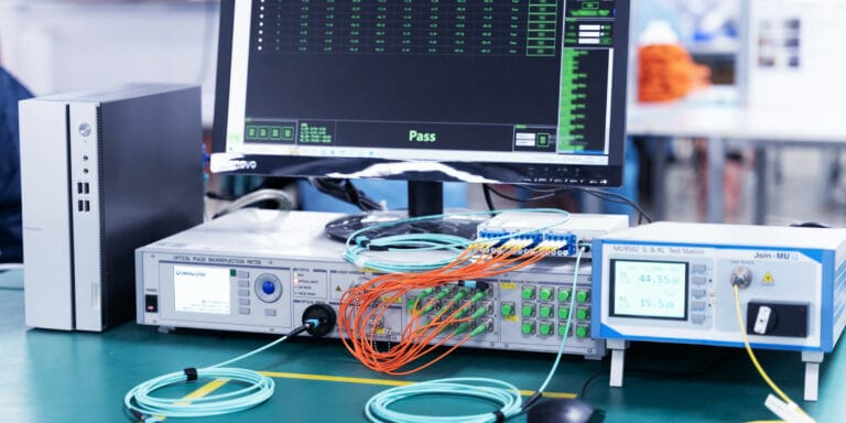
An optical loss test set (OLTS) — a light source and power meter pair — measures insertion loss directly by injecting a known optical power at one end of the link and measuring the received power at the other, with the difference giving the insertion loss figure. An OTDR (optical time-domain reflectometer) provides a more detailed picture, showing loss at each individual connector and splice point along the link as a trace, which is particularly useful for troubleshooting where a single problem connection needs to be located within a longer link.
Summary
Insertion loss measures how much optical power is lost as a signal travels through a fibre link — lower is better. Return loss measures how much light is reflected back towards the transmitter at connection points — higher is better. Both accumulate from fibre attenuation, connector loss, and splice loss along the link, and both must be accounted for in a proper loss budget calculation. OM4’s dominant loss contributor on typical short backbone runs is connector count rather than fibre attenuation, and its VCSEL sources are relatively tolerant of reflection. OS2’s lower per-kilometre attenuation supports much longer runs, but its narrow-linewidth laser sources make return loss — and therefore connector polish type — a significant specification decision, particularly for long-distance, PON, and DWDM applications where APC connectors are the standard choice.
If you need help specifying fibre components with the right loss characteristics for your installation, get in touch with the DTECH team — we supply OM4 and OS2 fibre cable, patch leads, and pigtails to installers and IT teams across the UK, Europe, and the Middle East.