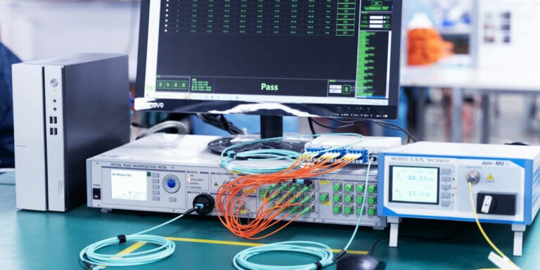
A fibre link can sit well inside its maximum distance and still fail, because distance is only one of the things that eats light. Every metre of glass, every connector and every splice removes a little optical power, and the receiver at the far end needs enough left to read the signal. The sum of those losses is the link’s insertion loss, and the most the application allows is its loss budget. Working this out before installation is the difference between a link that tests clean first time and one that gets re-terminated on site.
What insertion loss is, in plain terms
Insertion loss is the drop in optical power between the transmitter end and the receiver end of a passive link, measured in decibels (dB). The scale is logarithmic, which is why small numbers matter: 3dB means roughly half the light is gone, and 10dB means roughly 90% is gone. A link carrying an extra 1dB of unexpected loss has lost around a fifth of its power for no good reason.
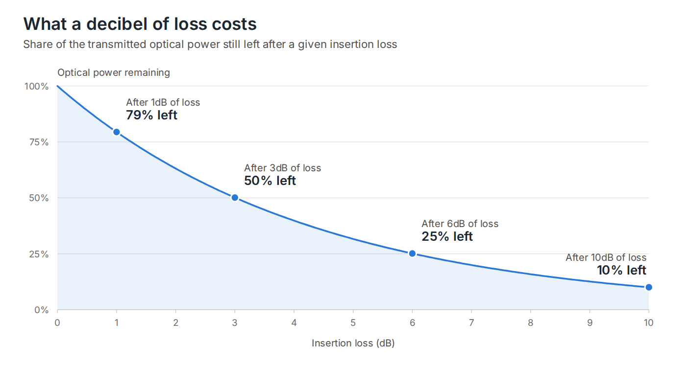
Light is lost in three places:
- Fibre attenuation: light absorbed and scattered along the glass, proportional to length.
- Connectors: each mated pair loses a little at the joint, through core misalignment, end-face quality and contamination.
- Splices: each fusion or mechanical splice adds a small fixed loss.
The loss budget formula
The calculation is a straightforward sum:
Total link loss = (length × attenuation per km) + (mated connector pairs × connector loss) + (splices × splice loss)
You then compare that total with the maximum channel insertion loss the application allows. If the calculated loss is lower than the allowance, the link has headroom; if it is higher, the link will not meet the application’s requirement however short it is.
Step 1: the component figures to use
For design calculations, the usual approach is to use the maximum values in the cabling standards rather than best-case figures. These are the figures published in TIA-568.3 for cabled fibre and for component allowances:
| Component | Wavelength | Allowance |
|---|---|---|
| OM3 / OM4 multimode cable | 850nm | 3.0dB/km |
| OM3 / OM4 multimode cable | 1300nm | 1.5dB/km |
| OS2 singlemode, outside plant cable | 1310 / 1550nm | 0.4dB/km |
| OS2 singlemode, indoor/outdoor cable | 1310 / 1550nm | 0.5dB/km |
| OS2 singlemode, inside plant cable | 1310 / 1550nm | 1.0dB/km |
| Mated connector pair (standard grade) | All | 0.75dB maximum |
| Fusion or mechanical splice | All | 0.3dB maximum |
Two things to note. First, the 0.75dB connector figure is a ceiling that standards-compliant connectors must stay under, not what a good connector typically achieves. Second, the singlemode cable figure depends on the cable construction class, so check which one applies to the cable you are actually installing.
Step 2: find the budget your equipment allows
The maximum channel insertion loss comes from the Ethernet standard for the transceivers you are using. These are the IEEE 802.3 figures for common applications:
| Application | Fibre | Max reach | Max channel insertion loss |
|---|---|---|---|
| 10GBASE-SR | OM3 | 300m | 2.6dB |
| 10GBASE-SR | OM4 | 400m | 2.9dB |
| 40GBASE-SR4 | OM3 | 100m | 1.9dB |
| 40GBASE-SR4 | OM4 | 150m | 1.5dB |
| 100GBASE-SR4 | OM3 | 70m | 1.9dB |
| 100GBASE-SR4 | OM4 | 100m | 1.9dB |
| 10GBASE-LR | OS2 | 10km | 6.2dB |
| 100GBASE-LR4 | OS2 | 10km | 6.3dB |
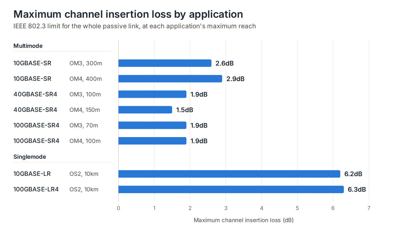
The pattern is worth noticing. Faster multimode applications have far smaller budgets, so a 40G or 100G link has little room for loss. Singlemode long-reach applications have a much bigger budget, but it is spent quickly over long distances.
Worked example 1: a 10G multimode link that passes on distance but fails on loss
An OM4 backbone run of 250m carries 10GBASE-SR through a cross-connect, so the channel has four mated connector pairs. At 250m, the distance is comfortably inside the 400m limit. The loss budget is 2.9dB.
| Component | Using standard allowance (0.75dB per pair) | Using low-loss connectors (0.3dB per pair) |
|---|---|---|
| Cable: 0.25km × 3.0dB/km | 0.75dB | 0.75dB |
| Connectors: 4 mated pairs | 3.00dB | 1.20dB |
| Total | 3.75dB | 1.95dB |
| Against the 2.9dB budget | Over budget by 0.85dB | Passes with 0.95dB spare |
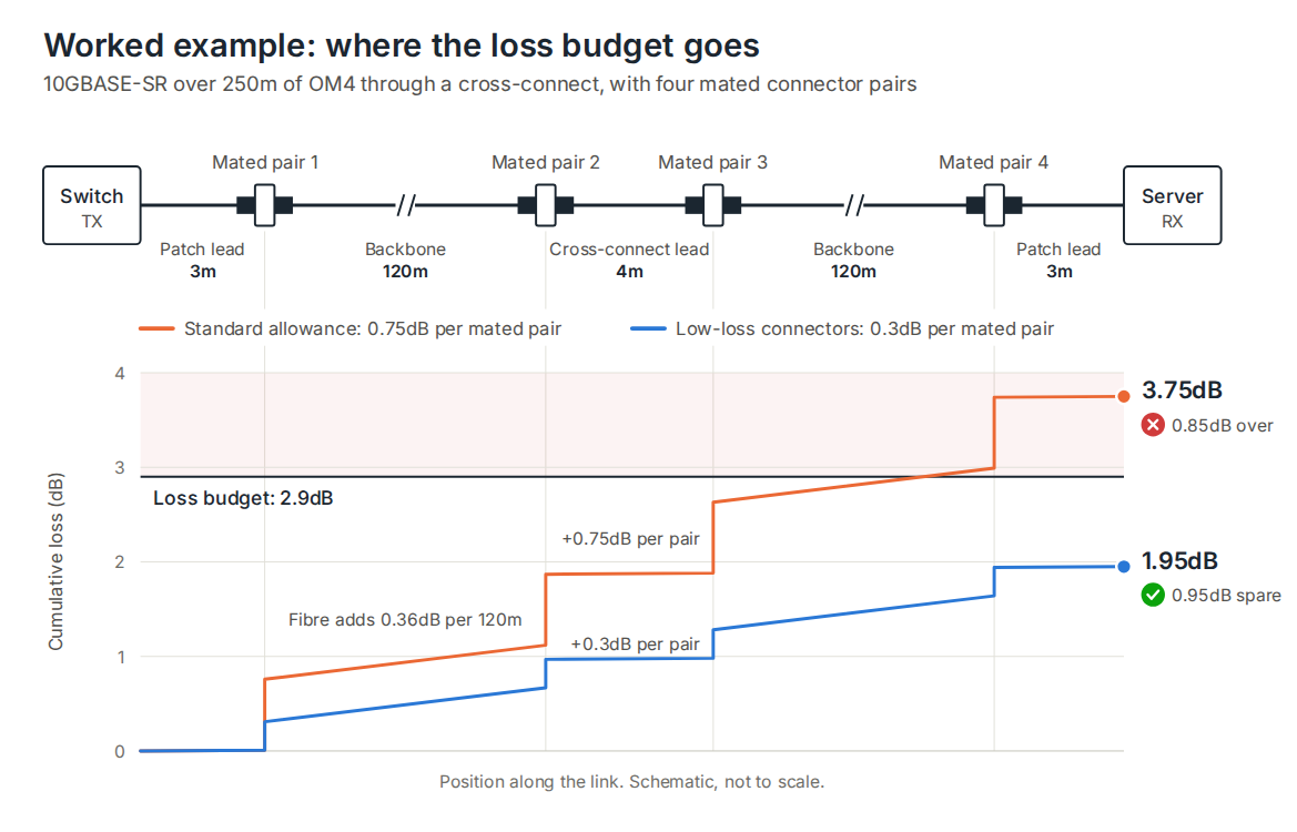
The cable is identical in both columns. The only variable is connector quality, and it decides whether the design works. This is why loss budgets matter more than maximum-distance figures: the 400m reach quoted for OM4 assumes a channel that meets the loss budget, and it is the connectors, not the glass, that usually use that budget up.
Worked example 2: a singlemode link close to the limit
An OS2 indoor/outdoor cable run of 8km carries 10GBASE-LR, with two mated connector pairs and one splice along the route. The budget is 6.2dB.
| Component | Loss |
|---|---|
| Cable: 8km × 0.5dB/km | 4.00dB |
| Connectors: 2 mated pairs × 0.75dB | 1.50dB |
| Splice: 1 × 0.3dB | 0.30dB |
| Total | 5.80dB |
| Against the 6.2dB budget | Passes with 0.4dB spare |
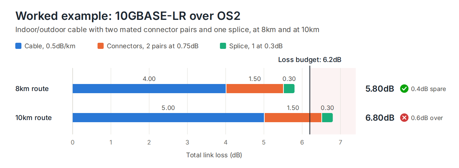
Stretch the same route to 10km and the cable loss alone rises to 5.0dB, taking the total to 6.8dB, which is over budget. A 10km reach figure can’t simply be assumed for every cable and connector combination; it has to be calculated for the actual link. Using the 0.4dB/km figure for outside plant cable, or connectors well under the 0.75dB ceiling, would change the answer, and that is exactly the point of doing the sum.
Where the loss really comes from, and how to reduce it
- Connector count: every extra mated pair is another 0.75dB on a worst-case calculation. Removing a cross-connect or using a longer single cable run is often the cheapest way to recover budget.
- Connector quality: factory-terminated, tested end faces are consistently lower loss than connectors fitted in the field. DTECH pre-terminated assemblies are typically ≤0.3dB per connector, against figures that can reach 0.5dB or more for field termination.
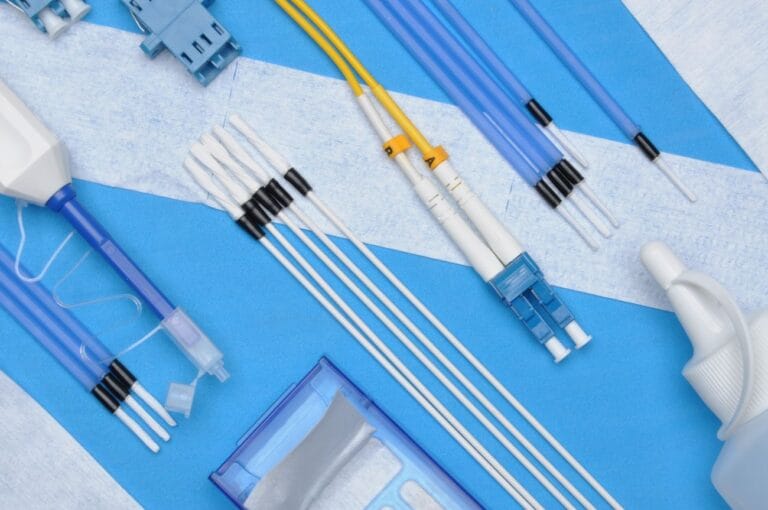
- Contamination: a dirty end face can add far more loss than the connector itself, and it is the most common reason a link that calculates fine tests badly. Inspect and clean before every mating.
- Splices: fusion splices are the lowest-loss option, with figures commonly well under the 0.3dB maximum, and singlemode fusion splices are often around 0.15dB.
- Bend radius: tight bends leak light out of the core. Bend-insensitive fibre tolerates more, but it is no licence to ignore minimum bend radius.
- Mismatched fibre: mixing OM3 and OM4, or 62.5µm and 50µm cores, adds loss at the joint.
Leave headroom
A calculation that lands exactly on the budget leaves nothing for the future. Connectors get re-mated and re-cleaned, cables get damaged and repaired with an extra splice, and test equipment has its own measurement tolerance. Where the maths allows, design the link with some margin, and treat any result within a few tenths of a dB of the limit as a risk.
Designing for a low loss budget with DTECH
The simplest way to protect a tight budget is to control the connector variable. DTECH pre-terminated fibre assemblies are UK manufactured, 100% factory tested and made to order in the length you specify, delivered in 2–4 days. Choose OM4 tight buffered for multimode links, or OS2 loose tube and OS2 CST armoured assemblies for singlemode and harsher routes.
Where the route needs bulk cable on site, the OM4 loose tube and OS2 loose tube cables are rated for both internal and external use, and the splicing accessories range covers the fast field connectors and splice trays to complete the termination. For the final connection to equipment, see the fibre optic patch leads.
Frequently asked questions
What is a fibre loss budget?
It is the maximum amount of optical power a link can lose between transmitter and receiver while still working. The calculated loss of the cable, connectors and splices must be lower than the loss budget set by the application’s standard.
How do I calculate insertion loss for a fibre link?
Add the fibre attenuation (length multiplied by dB per km), the connector loss (number of mated pairs multiplied by loss per pair) and the splice loss (number of splices multiplied by loss per splice). Compare the total with the maximum channel insertion loss for your application.
How much loss does a fibre connector add?
The TIA-568.3 maximum for a standard-grade mated pair is 0.75dB, which is the figure to design against. Good factory-terminated connectors are typically much lower, around 0.3dB or better.
What loss figure should I use for OM4 and OS2 cable?
For OM3 and OM4, use 3.0dB/km at 850nm and 1.5dB/km at 1300nm. For OS2 singlemode, use 0.4dB/km for outside plant cable, 0.5dB/km for indoor/outdoor cable or 1.0dB/km for inside plant cable, depending on the cable’s classification.
Why does my link fail even though it is within the maximum distance?
Because the distance rating assumes the whole channel stays within its loss budget. Too many connectors, poor-quality terminations, dirty end faces or tight bends can use up the budget well before the cable reaches its maximum length.
Is a fibre link with spare loss budget always better?
Yes. Spare budget absorbs later repairs, re-terminations and measurement tolerance, and it is the cheapest form of insurance a link can have.
Summary
Insertion loss is the sum of cable attenuation, connector loss and splice loss, and the maximum your link can lose is set by the application it carries. Calculate it before you install, using the standard allowances, and compare the result with the budget for your transceivers. Keep connector counts low, use low-loss factory-terminated assemblies where the budget is tight, and leave some headroom. A link that calculates comfortably will test comfortably.
Need help working out a loss budget for a specific link, or specifying the right assembly for it? Get in touch with the DTECH team.